
1. પરિચય
This manual provides essential information for the proper installation, operation, and maintenance of the Simplex 565-905 4098 4-Wire Duct Detector Board. This board is a critical component designed for integration into a 4-wire duct smoke detection system, facilitating early detection of smoke within HVAC systems to prevent the spread of smoke and fire throughout a building.
It is imperative that all personnel involved in the installation, testing, or maintenance of this device read and understand the contents of this manual completely. Adherence to these instructions ensures optimal performance and compliance with safety standards.
2. સલામતી માહિતી
Installation and servicing of this equipment must be performed by qualified and authorized personnel only. Failure to follow these safety guidelines may result in property damage, serious injury, or death.
- પાવર ડિસ્કનેક્ટ કરો: Always disconnect all power sources before installing, servicing, or removing the detector board.
- ઇલેક્ટ્રિકલ જોખમો: This device operates with electrical current. Exercise extreme caution to avoid electrical shock.
- સ્થાનિક કોડ્સ: All installations must comply with applicable local and national electrical and fire codes, as well as the authority having jurisdiction (AHJ).
- યોગ્ય સાધનો: Use only appropriate tools and equipment for installation and maintenance.
- કમ્પોનન્ટ હેન્ડલિંગ: Handle the circuit board with care to prevent damage from electrostatic discharge (ESD). Use ESD-safe practices.
3. ઉત્પાદન ઓવરview
The Simplex 565-905 4098 4-Wire Duct Detector Board is a printed circuit board designed to interface with a duct smoke detector head. It processes signals from the detector and provides outputs for alarm, supervisory, and test functions to a fire alarm control panel (FACP).
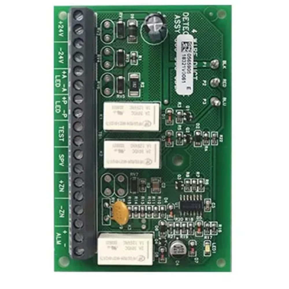
આકૃતિ 3.1: ફ્રન્ટ View of the Detector Board
This image displays the front side of the Simplex 565-905 4-Wire Duct Detector Board. Key components visible include the terminal block on the left for power and signal connections, various resistors, capacitors, and two relays (K1, K2). An LED indicator (LED1) is also present. The board is green with white silk-screened labels.

આકૃતિ 3.2: કોણીય View of Terminal Block
An angled perspective of the Simplex 565-905 4-Wire Duct Detector Board, providing a clearer view of the 18-position terminal block. Labels for connections such as +24V, -24V, LED, TEST, SPV, +ZN, -ZN, and ALM are distinctly visible, indicating various power, signal, and alarm connections.

આકૃતિ 3.3: પાછળ View of the Detector Board
This image shows the reverse side of the Simplex 565-905 4-Wire Duct Detector Board. It reveals the intricate circuit traces, solder points for components, and mounting holes. The text 'REV F' is visible, indicating the revision number of the board.

આકૃતિ 3.4: ઉત્પાદન પેકેજિંગ
This image displays the brown cardboard packaging for the Simplex 565-905 4-Wire Duct Detector Board. Labels on the box clearly indicate the Product ID (PID: 565-905), Description (4098 4WIRE DUCT DETECTOR PC BD), Part No. (0565905), and a detailed Serial Number (565-90505061912490936213651). This packaging confirms the product's identity and provides traceability.
4. સેટઅપ અને ઇન્સ્ટોલેશન
4.1 માઉન્ટ કરવાનું
The detector board is designed to be mounted within a compatible duct detector housing or an appropriate enclosure. Ensure the mounting location provides adequate space for wiring and access for maintenance. Use the designated mounting holes on the board for secure installation.
4.2 વાયરિંગ કનેક્શન્સ
Refer to Figure 3.2 for the terminal block layout. All wiring must be performed according to the system's design specifications and local electrical codes. Use appropriate wire gauges for all connections.
- +24V, -24V: Connect to a regulated 24V DC power supply from the fire alarm control panel or an auxiliary power supply. Ensure correct polarity.
- +A, -P: These terminals are typically used for specific auxiliary functions or sensor inputs, as defined by the complete duct detector assembly's documentation. Consult the main duct detector manual for specific usage.
- એલઇડી: Connect to an external remote LED indicator, if used. This LED typically mirrors the status of the onboard LED1.
- પરીક્ષણ: This input is used to initiate a functional test of the detector. Connect to a test switch or a test input from the FACP.
- SPV (Supervisory): Connect to the supervisory input of the FACP. This output indicates a trouble condition or a supervisory event.
- +ZN, -ZN (Zone): These terminals are for connecting to a detection zone on the FACP. They typically provide the alarm signal.
- ALM (એલાર્મ): This output provides the alarm signal to the FACP, usually through a relay contact.
After all connections are made, verify wire integrity and ensure no short circuits or open circuits are present before applying power.
5. ઓપરેટિંગ સૂચનાઓ
5.1 પાવર-અપ
Upon initial power application, the detector board will perform a self-diagnostic check. The onboard LED1 (and any connected remote LED) will typically flash or illuminate momentarily to indicate normal operation or a specific power-up sequence.
5.2 એલઇડી સૂચકાંકો
The LED1 on the board provides visual status indications:
- સામાન્ય કામગીરી: Typically, the LED will flash periodically (e.g., every 5-10 seconds) to indicate normal polling or standby mode.
- અલાર્મ સ્થિતિ: When smoke is detected, the LED will illuminate steadily (or flash rapidly) and the ALM output will activate.
- મુશ્કેલીની સ્થિતિ: A specific flash pattern or steady illumination (different from alarm) may indicate a fault or trouble condition (e.g., sensor fault, wiring issue). Refer to the complete duct detector manual for specific trouble codes.
5.3 પરીક્ષણ
To test the detector board and its associated smoke detector, activate the TEST input. This will simulate a smoke condition, causing the board to go into alarm. Verify that the ALM output activates and that the FACP receives the alarm signal. Reset the system after testing.
6. જાળવણી
Regular maintenance is crucial for the reliable operation of the Simplex 565-905 4098 4-Wire Duct Detector Board and the overall fire alarm system.
- દ્રશ્ય નિરીક્ષણ: Periodically inspect the board for any signs of damage, corrosion, or loose connections.
- સફાઈ: If dust or debris accumulates on the board, carefully clean it using a soft, dry brush or compressed air. Do not use liquid cleaners.
- કાર્યાત્મક પરીક્ષણ: Perform regular functional tests as per local codes and manufacturer recommendations to ensure the detector and board are operating correctly.
- સિસ્ટમ તપાસો: Ensure all associated components, such as the smoke detector head and FACP, are also maintained according to their respective manuals.
7. મુશ્કેલીનિવારણ
If the detector board or associated system is not functioning as expected, consider the following:
| લક્ષણ | સંભવિત કારણ | ક્રિયા |
|---|---|---|
| No LED activity, no power | વીજ પુરવઠો નથી, ખોટો વાયરિંગ, ખામીયુક્ત વીજ પુરવઠો. | Verify 24V DC power supply connections and voltage. Check wiring for shorts or breaks. |
| Detector in trouble (e.g., specific LED flash pattern) | Faulty smoke detector head, wiring issue to detector, dirty sensor. | Inspect smoke detector head and its connections. Clean the detector head if necessary. Consult the detector head manual. |
| ખોટા અલાર્મ્સ | Environmental factors (dust, humidity), incorrect sensitivity setting (on detector head), electrical interference. | Check the environment for sources of smoke or particulate matter. Verify detector head sensitivity settings. Ensure proper grounding. |
| Test function does not work | Incorrect wiring to TEST input, faulty test switch, issue with detector head. | Verify TEST input wiring. Test the switch. Ensure the detector head is functional. |
For issues not resolved by these steps, contact Simplex technical support or a qualified fire alarm technician.
8. સ્પષ્ટીકરણો
- બ્રાન્ડ: સિમ્પ્લેક્સ
- મોડલ નંબર: 565 905 4098
- યુપીસી: 072632856263
- પાવર ઇનપુટ: 24V DC (as indicated by board terminals)
- Power Source (as per general product category): બેટરી સંચાલિત (Note: This specification is likely inherited from a broader product category. The board itself requires a 24V DC system power supply.)
- એલાર્મ આઉટપુટ: Relay contacts (ALM terminals)
- Alarm (as per general product category): શ્રાવ્ય (Note: The board provides an alarm signal; an audible alarm is typically generated by a separate device connected to the FACP.)
- એકમ સંખ્યા: 1.0 ગણતરી
9. વોરંટી અને સપોર્ટ
For specific warranty information regarding the Simplex 565-905 4098 4-Wire Duct Detector Board, please refer to the original purchase documentation or contact your authorized Simplex distributor. Simplex provides technical support for its products. For assistance, please contact Simplex customer service or visit their official webઆધાર સંસાધનો માટે સાઇટ.


